Summary:The design and build of a Chain Oiler system. The original post was made by Descolada and can be found here. The extract shown here is a summary from the end of the thread where Des reports on the finished system. DIY Chain Oiler Project - How ToLiability: If you decide to follow these instructions you accept all responsability for the outcome. This is a guide and I have no control over the abilities of someone trying to replicate the process.Acknowledgement: I was inspired to do this project after watching the video by YouTuber "Render JM". You can watch the video here;
OverviewAs you may know I have an innate hatred of blatant profiteering on commercial products. I did not want to spend the kind of sums required to purchase one of the more popular chain oiler systems and I continue to read reports suggesting that they are not always as proficient as advertised. So I decided to try something of my own.
I estimate that my system cost no more than 25 UKP - not including the cost of a 5 Litre bottle of EP90.Parts List:1 x
Chainsaw fuel Primer Bulb.
1 x Aquarium air line tubing.
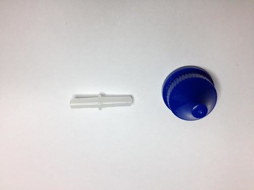
4 x straight through airline tubing connectors.
2 x right angle airline tubing connectors.
1 x Aquarium airline flow control valves.
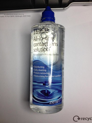
1 x Tesco 250ml All-In-One Contact lense Solution.
1 x 5ml Plastic Pipette / Dropper
1 x Large Jubilee Clip
1 x 12in length of copper earthing wire.
1 x Large bottle if EP90 gear oil.
Aluminium needed to fabricate a bracket. Here's a suggested supplier
Aluminium sheet plate 300 x 300 x 2 mm thick model engineering hobby bracket
Tools Needed:Disposable modelling knife or scalpel.
Dremel Drill (you could use a hand drill or a standard drill).
Clear Heavy Duty Packing Tape.
Assortment of cable ties.
A hot glue gun.
Construction:Reservoir Assembly.Begin by empty and cleaning the contact lense bottle. You may want to wash out the bottle and let it dry, but remember that this oil is not going into the engine, its just getting dropped onto the chain, so for the most part minor chemical contamination (from the contact lense fluid) isn't going to be an issue. More of an issue is debris created by the next step. This you must make every effort to remove or it may end up blocking the nozzle of the oil feed.
You need three holes in the bottle, two at the top and one at the nozzle end where the oil will flow out. The two at the top are for a refill tube, the other will form a vent to air.
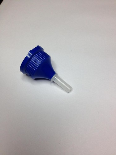
These holes are going to act as entry points for three 'straight through' aquarium airline tube connectors. Make them as snug a fit as possible and secure them using hot glue. The hot glue will hold them in place and also act as sealant to stop oil escaping around the connectors. The bottle will be upside down once in place so the 'top' where the bottle cap is screwed on will ultimately point down. As far as the oil outlet hole is concerned (where the blue screw on cap is located), I removed the screw cap, drilled out the plastic nozzle, hot glued the straight through connector in place and then drilled out the blue screw on cap. This was then re-attached and then sealed with more hot glue.
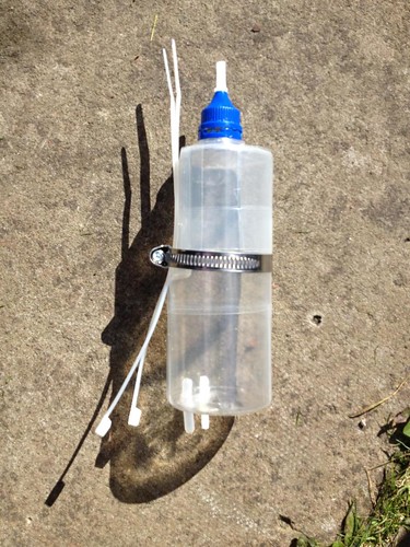
Here's the sequence in photos. The last photo shows the completed bottle with the jubilee clip from a later stage, but I am putting it in here so you can see the top two connectors in place. Just ignore the jubilee clip for now :-)
The Contact Lens Bottle
The straight through connector and screw on cap
Nozzle Holes Drilled
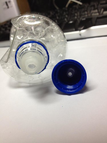
Completed Nozzle Assembly
Once all three holes have been drilled and the straight through connectors glued in place, reinforce the bottle using heavy duty packing tape. I have used clear tape because I want to be able to see how much EP90 is left in the bottle at a glance(from here on in I will refer to it as "the reservoir"). My reason for reinforcing the reservoir is to prevent any accidental penetration by something rebounding off the road and striking the side of the bottle, given its final location this is unlikely but I wanted to play safe. I really don't want all that oil to get dumped over the back wheel.
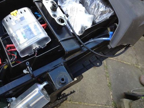
Mounting the Reservoir AssemblyI decided that the best place to mount the reservoir was behind the near-side rear cowling (is that the right name for it?). I first did a mock-up and held it in place with some cable ties in order to better judge the location and the clearance between the reservoir and the cowling.
Here's what it looked like;
Reservoir Mock-up photo
Reservoir Mock-up Top View

Once I was happy with this I added double-sided foam to the mounting spar (to avoid metal on metal damage) and the added a large jubilee clip to the reservoir to act as a mounting point. The natural shape of the reservoir means that the jubilee clip sits on a sort of 'ledge' that stops it from slipping down. Tighten the jubilee clip until it just starts to squeeze the reservoir and no tighter.
Support ProtectionTape protection
Jubilee Mounting
 Dispensing Nozzle/Applicator Assembly.
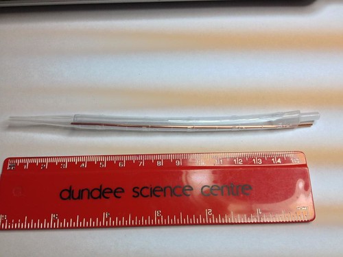
Take one of your 5ml Plastic Pipette/Droppers and cut off the priming bulb so you end up with the shaft and pipette end only. Next cut a length of aquarium air tubing - around 12cm will do, and finally a 13cm length of wire (I am using earth core stripped from some spare mains cable I had lying around).This all goes together as follows;
Push the straight through air pipe connector into one end of the tubing. Next partially insert the air tube into the open end of the pipette/dropper so that most of the tube runs down inside the pipette/dropper shaft. Before you push this all the way in, feed the wire down into the pipette/dropper shaft so it is
sandwiched between the airtube and the inner pipette body. Make sure to leave around 1 cm sticking out at the top. This can be curved over to stop it slipping all the way into the pipette, but in practice mine stayed where it was, even a month after it was attached to my bike.
Here's what the completed Dispensing Nozzle/Applicator assembly should look like.
Applicator Assenbly
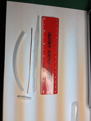
Applicator Completed Photo.
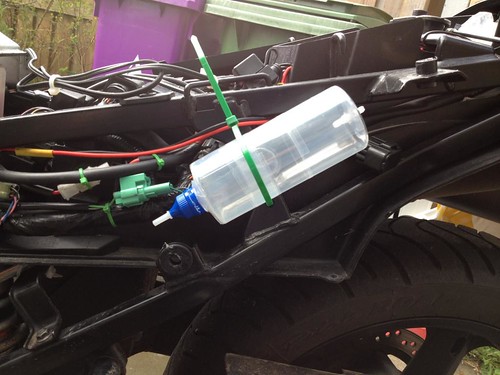
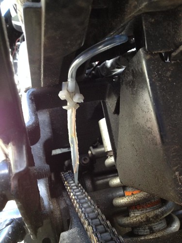
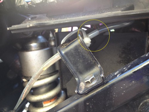
Once this assembly is complete position it under the frame bracket that sits on the nearside of the bike (it looks like it is part of the battery tray support.
I used two cable ties in a cross pattern to stop the applicator from moving around and the positioned the nozzle end about 3 cm over the centre of the chain. I figured that any higher and the oil would have far too much opportunity to miss, any nearer and you risk contacting the chain as it bounces up and down on the chain guide.
The wire core of the applicator nozzle will let you position the tube pretty much anywhere you want to to go. In the month I have been riding with this assembly either mocked-up or completed it has not moved position once.
Applicator assemble final position
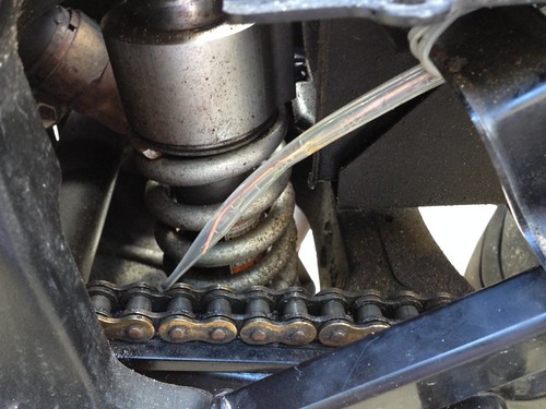
Applicator assemble final position
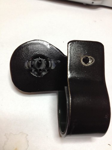
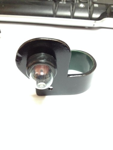
 Primer Bulb and Bracket Assembly.
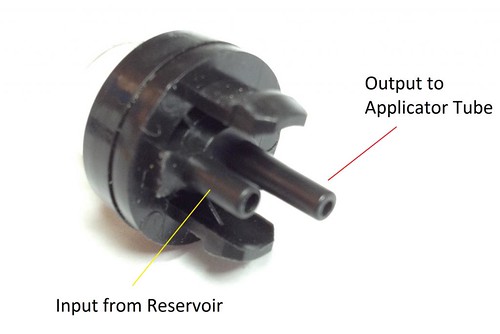
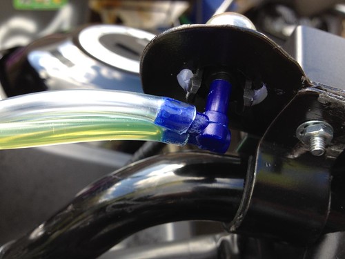
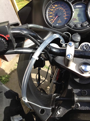
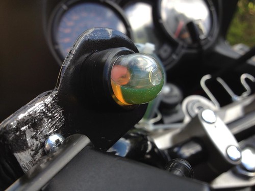
Placement of the primer blub is entirely open for personal preference, but I placed mine up by the heated grips control so it was easy to get to. The feed tubes are routed up by the handlebars on the left-hand side so to avoid over-straining the fragile input/output pipes on the back of the primer bulb I used a couple of aquarium air tube right-angle connectors to make the connections from the feed/flow tubes and the primer bulb.
The primer bulb I used seems to be a fairly standard thing and contains two pipes on the rear of the unit. The centre pipe is for the output flow (in our case, going to the dispensor/applicator assembly, the is the input feed from the reservoir.
Primer Bulb Input/Output Photo
The fit of the right-angled connectors wasn't ideal and I had to shave some of the outer material before the tubing would fit properly. The fit onto the input/output tubes on the primer bulb was also quite tight - so go gently here.
It needs to be tight enough not to leak, but not so tight that you break the damned primer bulb tubes trying to get the connectors in place.
I suggest you fit the right-angled connectors to the feed and flow airtubing before pushing them onto the back of the primer bulb, once they are on you don't want to have to take them off again. I didn't need to use any hot glue to keep these things in place, but you can add this step if you feel the need.
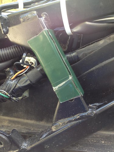
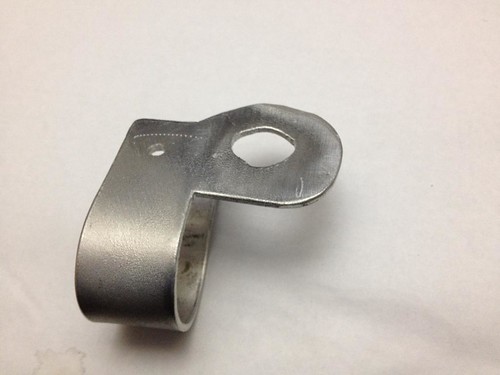
This assembly needs to be held in place somehow and I decided to fabricate a bracket that would hold the primer bulb while wrapping around the handlebar on the left-hand side.
I was pretty unhappy with what I ended up producing but wanted to get the job done so had to settle with this horrible piece of work. The gouging around the retaining bolt was caused by a pair of pliers trying to line up the bolt holes and clamping the bracket to make it a snug fit - I did it before the paint had properly cured. I also applied some double-sided foam to the inside of the part that connects with the handlebar - it adds a buffer to remove metal to metal damage.
Bracket Photos


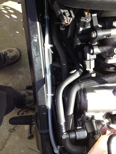
 Feed and Flow tube installation.
If you are matching my placement of the reservoir and the primer bulb, measure a length of aquarium airhose tubing to run from the reservoir down the side of the tank and up into the area where the primer bulb will be situated. Add a little extra to make sure you have enough to run all the way without snagging or causing sharp bends in the tube. Now cut another peice of exactly the same length as the first.
Using cable ties join the two lengths of pipe together - attach a cable tie approximately every 5 inches or so. When you have finished the tubes should act as single piece.
IN ORDER TO GIVE MYSELF ENOUGH ROOM TO JUDGE THE ROUTING OF THE PIPE I REMOVED THE SIDE PANELS AND THE TANK. YOU MAY DECIDE THAT THIS STEP IS UNNECESSARY - ITS YOUR CALL (I had some other work to do that was benefitted by removing these parts for easier access).
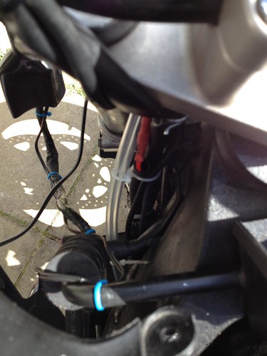
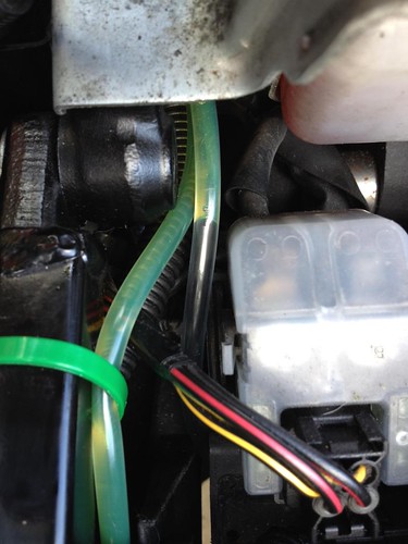
The key here is that the feed and flow "tube" (now they act as one) have to be kept away from the engine and secured so they don't hang down or otherwise create a 'snagging' opportunity. While the route from the reservoir to the top of the fuel tank is straight forward, you have to be very careful when routing around the headstock and up onto the handlebars. If you are not careful here you will encourage a situation where the pipe get's snagged or over stretched when you turn the handlebars from full lock to full lock.
Go over this several times until your are comfortable that you will not interfere with the free movement of the handlebar as it turns from one extreme to the other.Feed and Flow Tube Installation Pictures

 Attaching the Tubes - The Reservoir
You will need two lengths of tubing for the top of the reservoir, one for the filling tube and the other for an open to air vent. I also added a shut-off valve to the Filler Tube pipe to make sure that the only upper pipe open to atmosphere was the one I chose rather than a random event.
Filler Tube photo
The Open Air Vent tube should be attached somewhere high up and out of the way.
Reservoir Pipe Connections
 Attaching the Tubes - Dispensing Nozzle/Applicator Assembly
Connect the tube that routes up to the Output Flow connection on the primer bulb (that's the middle one) to the Dispansing Nozzle/Applicator Assembly.
Applicator Connection 1
Applicator Connection 2
You should now have the following;
- Reservoir mounted and associated tubes connected.
- Dispensing Nozzle/Applicator Assembly completed and attached to the bike with the feed tube connected.
- A twin "Feed/Flow" pipe running from the reservoir up to the primer bulb and then back down to the Dispensing Nozzle/Applicator.
- A bracket or some other method to support the primer bulb and the tube connections in place and secure on the primer bulb.
Now go back over the system you have just installed and check that it is securely fastened and will not touch or interfere with anything that might lead to an accident. Once you are happy with this we can move to prime the system.
Priming Procedure:The priming procedure consists of two phases. In the first part we fill the reservoir and suck the EP90 up to the primer bulb. In the second part we reverse the process and push the oil from the tube at the primer bulb output connection down towards the top of the Dispensing Nozzle/Applicator.
Here's how I did it.
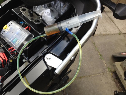
I had a 100Ml syringe lying about (it's a big Motherf*&(*^) and I filled this with EP90 chain oil. I then connected this to the Filler Tube that comes out of the reservoir and proceded to fill the reservoir (I think it took three syringe-full's). Once it was full I shut off the valve on that tube and removed the syringe from the tube.
Next I moved to the primer bulb and connected the syringe to the feed tube.
Using the suction of the syringe I drew EP90 from the reservoir up to the primer bulb stopping just short of the primer bulb so I could reattach the angle connector without getting oil in the joint connection.
I didn't use the syringe to prime the output tube (running down to the Dispensing Nozzle/Applicator) because I wanted to get an idea for how much oil the primer bulb would feed at any one time. So I used the primer bulb to push oil all the way down to the applicator.
Partly Primed
Filling the Tubes

The tubes start to prime
 Flow Control:
One of my biggest concerns was how I would control the flow of oil onto the chain. I wanted, at all costs, to avoid going to my bike only to find oil dumped on the floor, or finding that so much oil had dumped onto the chain that it splashed over the rear tyre.
It turns out that those fears were largly unfounded because the viscosity of the oil mixed with the vacuum caused by the primer bulb all act to limit the flow onto the chain. Testing has thus far shown that depositing an entire bulb onto the chain will result in a controlled application with a minor residual drain of the Applicator tube. This drainage is most likely a combination of gravity and capillary action in the Applicator tube assisted by the positioning wire.
Excess in the tube drains off gradually over a couple of minutes and is minor so there is not significant over application of oil.
Here's the applicator in action during a slow depression of the primer bulb.
I should really have cleaned the chain and sprockets thoroughly before starting these tests, but I didn't - so it is what it is. I spent much of this morning rectifying this oversight.
Observations:In testing this system I have dispensed oil onto the chain during multiple journeys, sometimes more than once in a day. To date I have seen no evidence of oil dumping onto the ground or rear wheel in significant amounts.
When oil is dispensed from the primer bulb bubbles appear in the primer bulb as it refills. I don't know where these are coming from because the system contains no observable leaks. These bubbles, however, are quite useful and can let you see that oil is being passed through the system successfully.
What I would do differently- Obviously, the bracket. I would redesign it and do a better job with the finishing.
- Placement. I remain concerned that some git passing the bike could just keep pressing the primer to see what happens and dump a container-full over the chain/floor/rear wheel.
- Feed/Flow tube routing. I think I would look again at the route taken from the reservoir to the primer bulb so as to make sure that it can not snag or foul the steering on the bike.
- I might look again at the location of the Dispensing Nozzle/Applicator. I have come to realise that part of the reason a Scotoiler dispenses its oil onto the rear sprocket may be because of the centrifugal action. This makes sure that the entire rear sprocket acts as an applicator and it may do a better job of getting oil onto the chain.
It's an interesting idea and I might look at it just as a pet project.
I hope some of you find this tutorial useful. <!-- s:thumb: -->

<!-- s:thumb: -->
